Help file for the G2 editor FMX

Introduction
This
is an editor for the Nord Modular G2 Synthesizer, that I made in my
spare time. With this editor you can make patches and upload or
download these to the synthesizer. It is an alternative for the
original editor from Clavia, the makers of the Nord G2 synthesizer.
The
current version is 0.3 Beta. I
reused most of the code from my earlier project, the NMG2 Open source
editor, so most of it is quite stable. The thing I changed is the user
interface, because my goal is to create an editor that can be used on a
tablet and on multiple operating systems.
v0.3 changes are marked with (v0.3)
Licence
This software is free for non-commercial use.
This is not commercial software.
This software is not associated with Clavia DMI AB.
This software is experimental, you can install and use this software only at your own risk.
Contents
- Help file for the G2 editor FMX
- Introduction
- Licence
- Contents
- Requirements
- Installation
- Installing on a Windows system
- Install and configure libusb-win32
- Install the Roboto font
- Download and unzip the editor
- Installing on a Mac OsX system
- Install the Roboto font
- Download fmx editor pkg file
- Running the application
- User interface
- Synth strip
- Slot strip
- Main window tabs
- Slot A, B, C and D
- Banks
- Patch settings
- Knobs
- Synth settings
- Application settings
- Using the patch window
- Adding and deleting modules
- Setting module labels
- Assigning module parameters to knobs
- Setting module color
- Adding and deleting cables
- Setting parameter properties
- Setting parameter labels
- Assigning MIDI controlers to parameters
- Copy variation
- Init Variation
- Default value
- Assign morphs to parameters
- Assign morphs to MIDI controllers
- Assigning individual parameters to knobs
- Patch file functions
- Init patch
- Load (Ld) patch
- Save (Sv) patch
- Load (Ld) performance
- Save (Sv) performance
- Using the pianoroll
Requirements
The current version of the editor can be installed on a Windows based system or a Mac OsX system.
Supported
Windows versions are XP, Vista, Windows 7 or Windows 8/8.1 system,
altough the graphics on a Windows XP, Vista or Windows 7 system don'l
look as good as on Windows 8/8.1.
On the Mac it should run on Snow Leopard and Mountain Lion.
You also need a Nord Modular G2 synthesizer.
The Clavia USB driver requirement is optional:
- If
you have the Clavia USB driver installed, you can configure
Libusb-win32 as a filter driver. This way you can keep using the
original Clavia editor.
- If you don't have the Clavia USB
driver installed and are not planning to do so, you can configure
Libusb-win32 as a stand alone driver.
Note: Installation of Libusb is only needed on a Windows system.
See next section on how to install.
Installation
For
the moment there is no installer, you can run the editor from the
directory where you unpacked the zipfile on Windows, or on the Mac you
can run the editor by dubbel clicking the pkg package.
Both on
Windows and the Mac it is recommended that you install the Roboto font.
This is a nice compact font that is developed for Android, and which
you can install freely on Windows or your Mac also.
On Windows
you need to install and configure the libusb-win32 package to be able
to comminicate over USB. On the Mac this is not needed, I included a
compiled library file in the package which might be all you need on OSX.
These steps are explained in the following sections.
Installing on a Windows system
- Install and configure libusb-win32
- Install the Roboto font
- Download and unzip the editor
Install and configure libusb-win32
Libusb-win32 is a generic USB driver that the editor uses for communicating with the G2 over USB.
First you have to download libusb-win32, goto the Libusb-win32-releases page and download the latest version of the bin package. On writing this helpfile the latest version is libusb-win32-bin-1.2.6.0.zip
Unzip the compressed file and you will find a directory structure like this:

Now open the bin folder, you will find a couple of new directory's

Now
you have to copy some files from these directories to your Windows
system folder, but this depends on the kind of computer you have:
If your computer is a X86 32 bits system:
- Open the x86 folder
- Copy the file libusb0_x86.dll to the Windows\system32\ folder and rename it to libusb0.dll
- Copy the file libusb0.sys to the Windows\system32\drivers folder
If your computer is a AMD 64 bits system:
- Open the amd64 folder
- Copy the file libusb0.dll to the Windows\system32\ folder
- Copy the file libusb0.sys to the Windows\system32\drivers\ folder
- Open the x86 folder
- Copy the file libusb0_x86.dll to the Windows\syswow64\ folder (this is the place for 32 bit dll's on a 64 bit system) and rename it to libusb0.dll
If your computer is a Intel IA64 bits system:
- Open the ia64 folder
- Copy the file libusb0.dll to the Windows\system32\ folder
- Copy the file libusb0.sys to the Windows\system32\drivers\ folder
- Open the x86 folder
- Copy the file libusb0_x86.dll to the Windows\syswow64\ folder (this is the place for 32 bit dll's on a 64 bit system) and rename it to libusb0.dll
This is all you have to do to install the libusb-win32 files on a Windows system.
The next step is very important, now you have to decide how you want to use Libusb-win32. You have two options
- Install Libusb-win32 as a filter driver
- Install Libsub-win32 as a new device driver
Installing
as a filter driver is the best option if you already have the Clavia
USB driver installed. The filter driver option as really a debugging
tool: Libusb will be connected as a debugging tool to the Cavia USB
driver. This means you can still use the original Clavia editor without
any problems, but you can also use the fmx editor. The only restriction
is that you cannot use both editors at the same time.
You can
easaly install or unistall the filter driver with the
"install-filter-win.exe" tool, which I will explain in the next
section.
Installing as a new device driver
is only used on computers where you don't have the Clavia USB driver
installed, and you also do not intend to do so in future. Basically you
will install a complete new driver for the G2 which will be
automatically selected by Windows as the prefered driver as you
connected your G2 to the computer. The original edtor will not be able
to connect to the G2 with this driver installed.
Option 1 : Configure LibUSB as a "filter driver":
This is the option you would choose if you already have the Clavia USB driver installed.
Connect your G2 and turn it on.
Go to the bin subfolder describing your system:
If your computer is a X86 32 bits system:
- Open the x86 folder
- Run program "install-filter-win.exe"
If your computer is a AMD 64 bits system:
- Open the amd64 folder
- Run program "install-filter-win.exe"
If your computer is a Intel IA64 bits system:
- Open the ia64 folder
- Run program "install-filter-win.exe"

In the wizard, choose "Install a device filter"
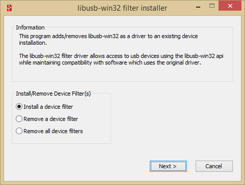
In the selection box, select the Clavia USB driver. If you have multiple G2's you have to do this for each instance.

Click "Install"

The same program lets you uninstall the filter driver.
Option 2 : Configure LibSUSB as a new device driver:
If
you do not have a Clavia USB driver installed on your system and are
not planning to do so, you can configure LibUSB as a device
driver.
Turn on the G2. Windows will probably prompt with the
"new hardware found" window, for which it wants a driver. Now we can
create an ".inf" file by running the programm "inf-wizard.exe", located
in the folder bin folder of the libusb package.


In the inf-wizard, first select the "Nord Modular G2" device.

The next thing is to provide a name of the driver, for example "Libusb G2 driver", than save the inf file.

Finally
you can directly install the driver by clicking "Install" or you can
point the Windows "New hardware found" wizard to the newly created inf
file.

Install the Roboto font
You can download the Roboto font from this location.
The website contains instructions how to install the font.
The editor uses the font "Roboto regular", so you should at least install that one.
Download and unzip the editor
Download the latest version from this location, unzip it somewhere on your disk and run program "G2_editor_FMX.exe"
Installing on a Mac OsX system
- Install the Roboto font
- Download fmx editor pkg file
Install the Roboto font
You can download the Roboto font from this location.
The website contains instructions how to install the font.
The editor uses the font "Roboto regular", so you should at least install that one.
Download fmx editor pkg file
Download the latest version from this location, double click or open the package file "G2_editor_fmx." should launch the application.
Running the application
When the application is started it follows a number of steps to initialize the editor. These steps are the following:
- It
tries to load the LibUSB library. If it fails the application displays
the following message "<libarry name> not found, USB functions
are disabled", but will continue to load.
- It loads the file
"Symbols.svg" from the application path, this contains svg images,
waveforms, arrows and so on, that are displayed on the various controls
- It loads the file "ModuleDef_v3.xml", which contains the module definitions
- It loads the file "ParamDef_v3.xml", which contains the parameter type definitions
- It loads the file "ModulePanelDefs.txt", which contains the layout of the module panels.
- Then it iterates through all the G2 devices it finds on the USB ports.
- For each G2 device a message interogation loop is started to load all the data from the G2 into the editor.
User interface
The
user interface is made out of frames and tabs. It is made so most
functions can be operated using point and click or gestures. Most of the short cut
keys of the original Clavia editor should work also. I have tried to
make the controls big so you could operate them on a touch screen. Also
the patch window can be zoomed.

Synth strip

On
the top row are located the so called "synth strips". For every G2 that
is found on the USB ports a synth strip is added. The editor can hold
max three synths for the moment. In the picture there are two synths
connected.
From left to right these are the controls on the synth strip:
- Activity
indictor, this is gray in the picture, but when there are messages
exchanged between the G2 and the editor this lights up green. When
connection is lost with the G2 this turns red.
- Label with name
of the G2 synth. This label has a green border when the synth is
currently selected in the editor. You can select synths by clicking on
the label.
- Edit box with the current performance name. You can change the performane name by editting and then pressing enter.
- Master clock BPM, change with the left/right buttons.
- Master clock run on or off
- Keyboard split on or off
- Performance mode on or off
See Clavia G2 manual for the functions 4 to 7.
Slot strip

Below
the synth strips are the slot strips A, B, C and D. The currently
selected slot has a blue background color. Each slot strip contains the
following controls:
- Slot label, click on this to select another slot. You can also change slots by typing A, B, C or D on the keyboard.
- Patch
name edit box, you can change the name by typing in the box and then
pressing enter. The patch name is also the file name for the patch if
you save it to disk.
- Slot enable on or off (see Clavia G2 manual)
- Slot keyboard on or off
- Slot hold on or off
- Variation selection buttons 1..8. These you can also operate using the keyboard, keys 1 to 8.
- Edit all, you can activate this momentarily if you want to change a parameter in all 8 variatrions at once.
- Patch volume
- Patch mute on or off
- Patch voice count.
- Patch
load, the top row is for the VA location, the bottom row for the FX
location. Note: this is not as accurate as on the original Clavia
editor, the meaning of the patch load message is not fully understood yet.
Main window tabs

Below the slot strips is a row named tabs. With these you select the frames with the correspnding name in the center pane.
Slot A, B, C and D
The first four tabs select the patch windows of Slot A to D. These will be explained in section "Using the patch window"
Banks

The Banks frame allows you to store and retreive patches and performances from the G2 internal memory banks.
This frame contains the following controls from top left to right bottom:
- Patch type control, a Patches or Perfs selection button.
- Bank
selection control, if Patches is selected then the bank selection
control shows 32 banks, if Perfs is selected then it shows the 8
performance banks
- Memory location selection control. When a memory location contains
a performace or patch it is colored else it shows the text ..Empty..
and a light gray color
- Retreive button, in case a memory location
containing a performance is selected, the performance is loaded. If it
contains a patch then the patch is loaded in the slot represented by
the currently selected slot strip.
- Store button, if the patch
type Perfs is selected the performance is stored in the selected memory location,
else if Patches is selected the patch from the selected slot is stored
in the selected memory location. If the slot already holds a patch or performance
then a dialog messages is shown: "Replace patch?"
- Clear button, the selected slot is cleared, you will get a warning message first.
- Ld bank, Sv Bank these buttons are not connected yet.
Patch settings

On
the patch settings frame you can set the patch parameters, Arpeggiator,
Vibrato, Glide, Bend, Sustain pedal and Octave shift. These are all
explained in the Clavia G2 manual.
On the top there is a
keyboard visible. With this keyboard you can set the keyboard range of
the currently selected slot. Click on the lowest key and with the mouse
key hold down, move to the highest key in the required range.
Knobs

The
knobs frame corresponds with the parameter pages window of the original
editor. I replaced rotary knobs with sliders in this frame.
There are a couple of differences with the original editor:
- Apart
from the normal parameter pages and the global parameter pages, you can
also select the "Morph" and "Patch" parameters pages.
- (v0.3)
There are little edit boxes associated with the sliders and buttons. In
these edit boxes you can enter a Midi CC value. If you enable "Auto
assign Midi" in the application settings, then on patch load the
application will automatically assign that Midi CC value to the
parameter associated with the slider or button. Note that the patch will be
changed by this, because controller assignments are part of a patch, so
you should only enable this function if you agree to that.
I use
this because I have a G2 engine and want to use it in combination with
a BCR2000, for example I always want the Arp on/off parameter
automatically assign to Midi CC 106 when I load a patch.
The Midi CC values that you associate with the sliders and buttons are stored in the ini file (g2editorfmx.xml).
Synth settings

The
synthesizer settings of the currently selected synth can be modified in
the Synth settings frame.The settings are
all explained in the Clavia G2 manual.
To change settings in edit boxes, type the value in the box and then press enter.
Application settings

The last frame is the application settings frame, on the top panel you can set some perferences:
- GUI settings
- Splitter visible button, indicates if the patch window should be split with a splitter bar into a VA and a FX location
- Zoom setting 1,2 and 3 edit boxes, with these you can define 3 zoom settings for the patch window.
- Knob control button, here you can set the control type for rotary knobs.
- Cable style, flat or gradient, just a display preference.
- Patch
directory, here you can enter the root folder of your patch files. With
this the editor can show a treeview of the folder structure of your
patch files.
- (v.03)
Auto assign midi. If enabled, this will automatically make Midi CC
assignments in the patch on patch load, see details in section Knobs.
- Init defaults. This sets the application settings back to the default.
Below that, one or more tabs for each G2 that the editor finds on the USB ports;
- USB
Connection button, normaly this would be set to Yes. Although it is
possible to connect to another editor as a TCP-IP cliënt, because maybe
the device the editor runs on doesn't support an USB connection to a
G2. In that case USB connection would be set to Off and you would enter
an IP addess and a Port of a host computer which runs an editor with
the actual USB connection to one or more G2 synths.
- Network
connection, so in case the editor is configured as a client to another editor, the host
edit box holds the IP address of the host editor and the port edit box
must be set to the port of the host editor.
- The Log buttons are used for debugging purposes, for example to check if patch and message structures are created correctly.
Alle
these settings are stored in a ini file named "g2editorfmx.xml". On
Windows this ini file is located in the application folder, on OSX this
file is located in the documents folder.
If you experience problems when starting the application, you can try to delete this file.
Using the patch window
In
the FMX editor patching is done in the patch frame in combination with
the patch function tabs on the right panel and the bottom row buttons.
The following patching functions are available in the editor:
- Adding and deleting modules
- Setting module labels
- Assigning module parameters to knobs
- Setting module color
- Adding and deleting cables
- Setting parameter properties
- Setting parameter labels
- Assigning MIDI controlers to parameters
- Copy variation
- Init variation
- Assign morphs to parameters
- Assign morphs to MIDI controllers
- Assigning individual parameters to knobs
- Init patch
- Load patch from disk
- Save patch to disk
- Load performance from disk
- Save performance to disk
Adding and deleting modules

When
you select the patch function tab "Add module" and click on a template
module in the list, a green rectangle will appear in the patch frame.
This rectangle will take the size of the module you selected.
Double
click the module, or Ctrl+Enter will add the selected module to the
patch. The green rectange will move to an empty space under the added
module.
You can click on another location in the patch frame to move the green rectangle.
When
you click on an existing module in the patch, the patch function tab
"Module" will be selected automatically in the right pane.

In the module tab, there
are the name and the module label on the top of the module frame. Below
these are another three tabs, Action, Knob assign and Color.
On
the Action tab there are a couple of buttons for basic selecting and editing
functions:
- Select multiple, this is meant for tablet use, to be able to select multiple modules you can enable this button
- Select all VA (Ctrl+A), select all modules in the VA section
- Select all FX (Ctrl+A), select all modules in the FX section
- Copy (Ctrl+C), copy selected modules
- Cut (Ctrl+X), cut selected modules
- Delete (Delete), delete selected modules
- Paste (Ctrl+V), paste modules from copy buffer
- Paste params (Ctrl+E), paste parameter values
- Undo (Ctrl+Z), undo
You
can also apply these actions on multiple modules. You can select
multiple modules in the patch window by:
- Holding Shift down while
clicking on modules
- By holding Ctrl down and after clicking on an
empty space in the patch, dragging a green selection window over the
modules
- Or by clicking Select Multiple and click on the modules you want to include in the selection.
You can move a module or modules by clicking on a module and dragging it to another place.
The button Pianoroll can be used if you have selected a Note sequencer module. See Using the pianoroll section.
Setting module labels
Select the module and edit the module label edit box and press enter. This can only be done if just one module is selected.

Assigning module parameters to knobs
To automatically assign all parameters of a module to knobs:
- Select the module
- On the Module patch function tab, select the sub tab "Knob assign"
- First select the Parameter page, A, B, C, D, E or E
- Then click on a Parameter page column index 1, 2 or 3.

If
you switch to the Knobs frame and select the corresponding Parameter
page and Parameter page column, you will see that the parameters are
assigned.

You
can follow the same procedure using the "Global knob assign" buttons,
to assigned the module parameters to the global parameter pages.
Setting module color
- Select the modules for which you want to change the color
- On the module patch function tab, choose the Color subtab
- Click on the desired color

Adding and deleting cables
When
you click on a connector, a yellow strip will appear in the patch
window. This means that the application is in "Cable drawing mode". You
can exit Cable drawing mode by pressing the Cancel button on the yellow
strip, or you can draw a cable by clicking on another
connector.

When
you click on a connector that is already connected through one or more
cables, there will be a selection button right next to the label
"Delete cable to". This selection button lets you select which of the
cables from the connector you want to delete.
You can also press Delete on the keyboard, which will delete all cables from the selcted connector.

Setting parameter properties
If
you click on a control that is connected to a parameter, the patch
function tab "Param" will be automatically selected. With the knobs,
edit boxes and sliders on this tab you can set a number of parameter
properties, which will be explained in the following sections.
Setting parameter labels
- Select a parameter
- On the patch function tab, edit the label in the parameter label edit box and press Enter.

Assigning MIDI controlers to parameters
- Select the parameter you want to assign a Midi controller to
- On the patch function tab "Param" select the sub tab "Actions"
- Type the Midi CC value in the edit box and press Enter
- Press the button "Assign CC"

You
can also use a "Midi learn" function. Note that you have to enable "CC
Receive" on the Synth settings frame for this. If so, just turn the
knob on your controller and the Midi CC edit box will show the received
Midi CC. Press the Assign CC button to assign the controler to the
parameter.
If a parameter already has a Midi CC assigned, the
text on the Assign CC button wille change to Deassign CC
<number>. If you press the button the controller will be
deassigned from the parameter.
Copy variation
On
the same Actions sub tab of the patch function Param tab, you will find
buttons to copy variations. The currently selected variation is
disabled. Click on one of the other buttons to copy the parameter
settings of the current variation to the selected variation.
Init Variation
Press
"Copy to init" to copy the current variation to the init buffer. You
can initialize a variation with the init buffer by pressing the "Init
variation" button.
Default value
If pressed will set the current parameter to the default value
Assign morphs to parameters
To assign a Morph value to a parameter:
- Select the parameter
- Choose the "Morph assign" tab, on the patch functions Param tab.
- Move the slider of the Morph source you want to assign to the parameter.
In
the patch window, all the parameters that have an assignment to the
selected morph source slider will indicate the assigned morph value in
red.
The parameters that ara assigned to another morph source will turn blue.

Assign morphs to MIDI controllers
You can also assign a Morph source to another Midi controller than the standard midi controller associated with the morph.
For this, select the Knobs frame and select Morphs in the bottom left selection button.
Click on the slider indicating the Morph source you want to assign a Midi controller to.
Goto
the patch function tab "Param", sub tab "Actions" and put in the Midi
controller number or use the midi learn function and then press Assign
CC.

Assigning individual parameters to knobs
To assign an individual parameter to a knob:
- Select the parameter
- On the patch function tab "Param", choose sub tab "Knob assign
- Click the Parameter page selection button A, B, C, D or E
- Click the Page column 1, 2 or 3
- Finally click the Knob index button. The knob index buttons that already have a parameter assigned will be disabled
If
a parameter is already assigned to a particular knob, the corresponding
button will be blue. To deassign the parameter from the knob, just
click the button again.
To assign a parameter to the global parameter pages, use the "Global knob assign" buttons.

Patch file functions
The
last tab on the patch functions pane is the Patch tab. On this tab are
located functions to initialize a patch and load and save patches and
performances to disk.

The
tree view will read the directory structure from the root patch
directory that you have set in the "App settings" frame. if you push
the button "Refresh", the treeview will be refreshed.
Init patch
This will initialize the currently selected slot with a new empty patch.
Load (Ld) patch
Selected a patch in the treeview and click on the "Ld patch" button, to load the patch in the currently selected slot.
Save (Sv) patch
The
patch of the currently selected slot will be saved in the selected
directory in the treeview if you push the button "Sv patch". The name
of the patch entered in the patch name edit box of the slot strip will
be used as the filename.
Load (Ld) performance
The performance selected in the treeview wille be loaded if you press the button "Ld perf".
Save (Sv) performance
The current performance will be saved in the selected directory in the treeview if
you push the button "Sv perf". The name of the performance entered in the
performance name edit box of the synth strip will be used as the filename.
Using the pianoroll
If
you click on a "Note sequencer" module in the patch window, the
"Pianoroll" button will be enabled on the patch function tab "Module",
sub tab "Action".
If you press this button a piano roll frame
will open. This is just a more convenient function to enter a melody on
the note sequencer module.

Clicking on the pianoroll window will move notes to the clicked location. Clicking on a note will turn the note on or off.
On the bottom of the pianoroll are a couple of buttons:- Transpose, will move all the notes one tick up or down
- Rotate, will move alle the notes one tick left or right
- Random, will randomize the notes
- Clear, will set all notes to E4
- Close, will close the pianoroll frame.
2014 B.J.H. Verhue
BVerhue@gmail.com