How well does Claude perform on converting bitmap images to SVG? I probably shouldn’t have been surprised that also in this area it does a very decent job. Maybe it is my age, but I am still a bit hesitant on using AI, although when in comes to programming, there is no denying that AI tools like Claude have become very very good. So how does it perform on SVG?
I found this jpeg image of a diesel engine model.
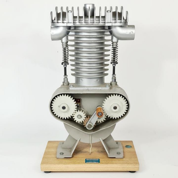
Then I asked Claude (Opus) the following question:
“File [Image #2] is a picture of a diesel engine. Can you convert this to an animated SVG file?“
Claude:
“That’s a nice single-cylinder demonstration engine — finned head and barrel, two spring-loaded pushrods, and an exposed gear train driving the cam gears. I’ll build a stylised vector version of that composition with the mechanism animated (SMIL, so it works both in a browser and in your control).”
I already find amazing that Claude can recognize all that from a bitmap image. Then, after 8min 48s it produced the following SVG:
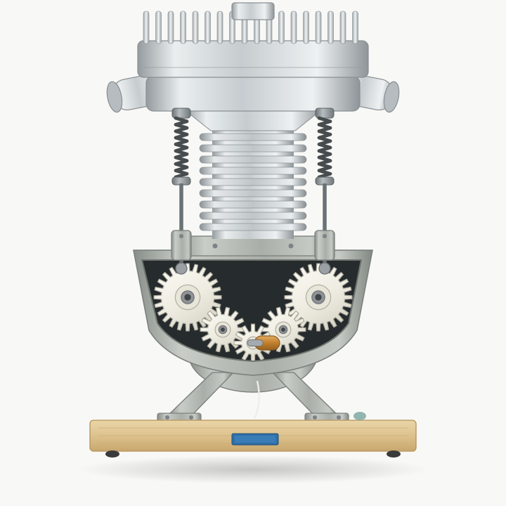
Overall I think this is a nice result. It figured out the moveable parts and their functions and how they should interact. I think the cylinder head especially the in- en output pipes could be improved upon.
Claudes own assessment on the conversion:
“It’s a stylised reconstruction, not a trace. I matched the composition, proportions and palette — finned head with the comb fins on top, side ports, finned barrel, gear housing with the dark opening, splayed legs, wooden base with the blue plate — but every shape is drawn from primitives. A faithful trace of the photo’s castings would need an autotrace pass over the bitmap, which produces thousands of unlabelled paths you can’t animate. Tell me if you’d rather have that instead.”
Next I asked to convert another image:
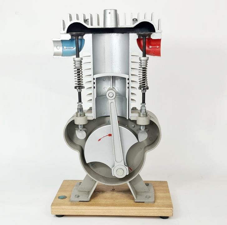
“Can you make a SMIL animated SVG file from [Image #3]“
Claude:
“Excellent — this cutaway is a much better animation subject, since the actual slider-crank is visible. I’ll compute real slider-crank kinematics and bake them into the SMIL values lists so the piston and con-rod move exactly right.”
Result after 7min 12s::
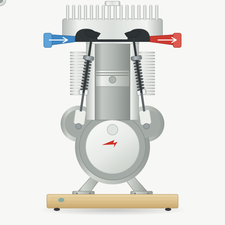
This is not quite right, the push rods for the valves don’t function correct and the drive shaft rotates the wrong way.
I asked Claude to fix the errors:
“There are some errors in the SVG. The first error is that the drive shaft rotates in the wrong direction, the red arrow in the picture shows the direction it should turn. Also you didn’t model the arrow correct in the SVG. The second error is the animation of the valve push rods. These should be pushed from below, against the upper constraints. The pushing from below should be done by the camshaft of which the ends we see in the picture and on the ends are the cam lobes that you also did not include in the SVG.”
Claude:
- Rotation direction — flip the crank to counter-clockwise, and draw a proper arrow instead of my scribble.
- Push rods pushed from below — the assembly must travel up against a fixed upper spring seat, not down.
- Missing cam lobes — those are the camshaft ends in the crankcase lobes; I’ll model real lobes and derive the lift from the actual profile.
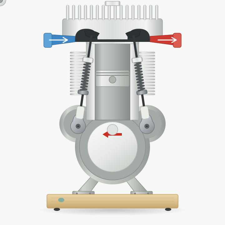
Better, though I am not really happy with the valves because they don’t really open and close the input and output, but I will leave that for now.
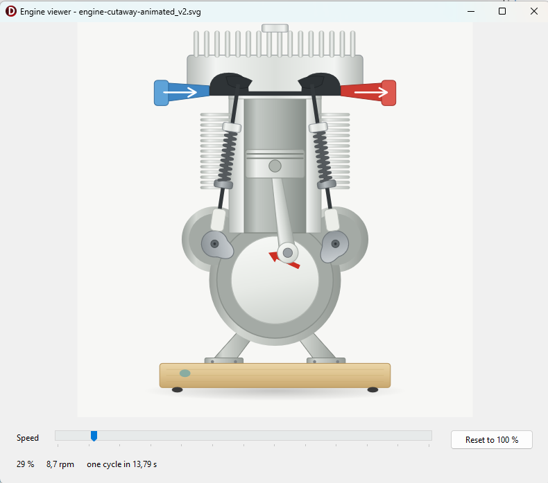
Next I am interested in building a Delphi application with the SVG library in which I can interact with the SVG. So my question to Claude:
“I would like to create a Delphi VCL application in which the SVG is displayed in a TSVG2Image control and in which i can control the rotation speed of the engine by a TTrackBar control.”
After 8min 27s Claude produced this application, which indeed works:
Finally I want to combine the two SVG’s into one:
“Can you now combine diesel-engine-animated.svg with engine-cutaway-animated_v2.svg in one svg in which the models are placed side by side. All the parts should match in position and movement. The new SVG should be used in the EngineViewer application. Make sure the valves really close the input and output openings, they currently overshoot the openings.”
After 16min 7s the following SVG:
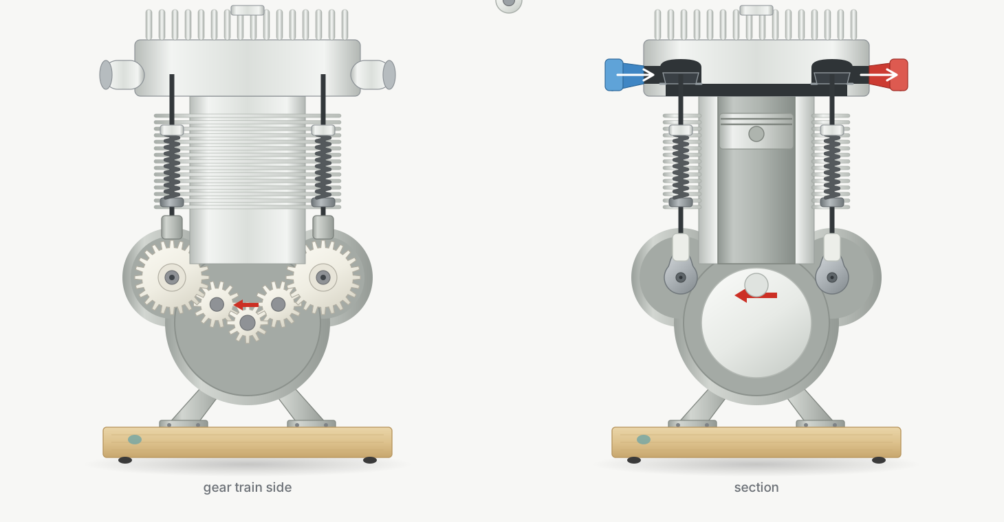
You could argue that the engines should rotate in opposite directions, but Claude made this intentionally:
“One thing I decided rather than asked: both views turn the same way. Strictly these are opposite sides of one engine, so the gear-train side would turn mirrored. I kept them visually identical since “match in movement” reads as phase agreement, and opposing arrows would look like a mistake. Say the word if you’d rather have the true mirrored direction — it’s a one-line change to the left view’s spin.”
And the application:
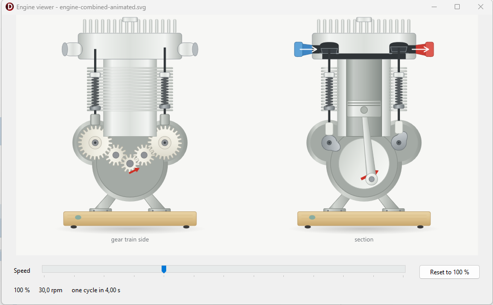
You can find the SVG files and EngineViewer project on github.
Concluding, my observation is that Claude is very capable in creating SVG images from bitmap images. The amazing thing for me is that it can figure out what a bitmap image represents. The job of constructing the SVG is somewhat less surprising to me because SVG is a more structured format and looks a bit more like programming.
Claude makes mistakes, that is obvious, so fortunately we humans are still needed. In my experience with Claude, it will try to do exactly what you ask but often makes suggestions or assumptions where you are not explicit and these I often find helpful, so I often keep some room for maneuver in my initial question and make my follow op questions more explicit.