Implement Zoom And Pan on TSVG2Image

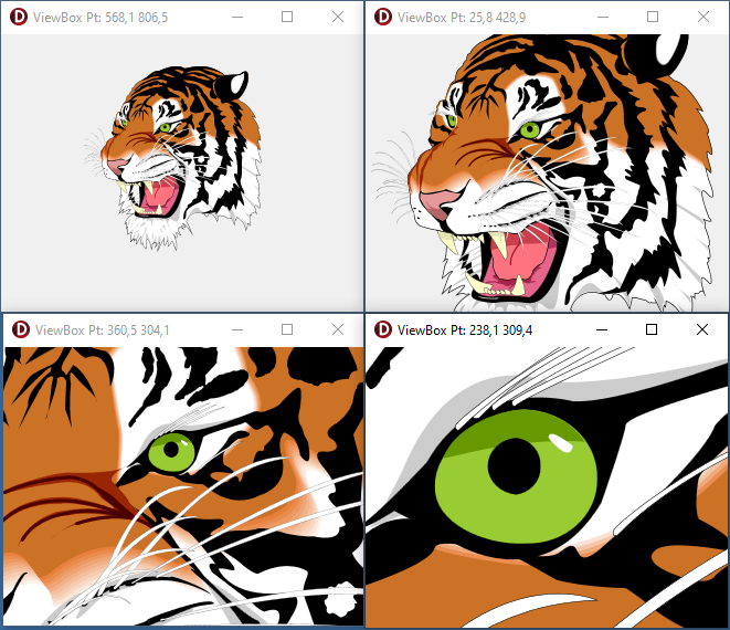
This example shows how Zoom and Pan can be implemented on the TSVG2Image control.

In SVG zooming and panning is controlled by the viewPort, viewBox and preserveAspectRatio attributes on the outer SVG element.

The outer SVG element is the first SVG element in the xml file. In most cases, there is only one SVG element within an SVG xml file.

View port

The viewPort is the window in which the SVG image is displayed. The viewPort is defined by the dimensions of the outer SVG element, so the width and height attribute or, if width and height are expressed as percentages, the client rectangle of the SVG’s container.

For our purposes we will override the width and height attributes of the outer SVG element and set them to 100%, so width = 100% and height=100%. With these settings the viewPort will be equal to the ClientRect of the TSVG2Image control.

View box

The viewBox attribute selects the part of the SVG image that is displayed. This is an optional attribute, not all SVG images have a viewBox defined.

For zooming and panning we need a viewBox, so if the SVG image has no viewBox defined, we will create one and initially set it to the same size as the viewPort.

Preserve aspect ratio

The preserveAspectRatio defines how the viewBox is aligned within the viewPort. We want to preserve the aspect ratio of the SVG image and we want the center it. For this we need the setting xMidYMid.

Basics of zooming and panning in SVG

For zooming and panning an SVG image we only need to modify the viewBox attribute.

For panning we simply change the top left point of the viewBox rectangle.

For zooming we change with equal proportion the width and height of the viewBox rectangle. The smaller the viewBox, the more we are zooming in.

Structure of the example application

  • A form with on it one TSVG2Image set to align “alClient” to the form
  • Property “DoubleBuffered” on the form is set to “True”, to ensure smooth zooming and panning
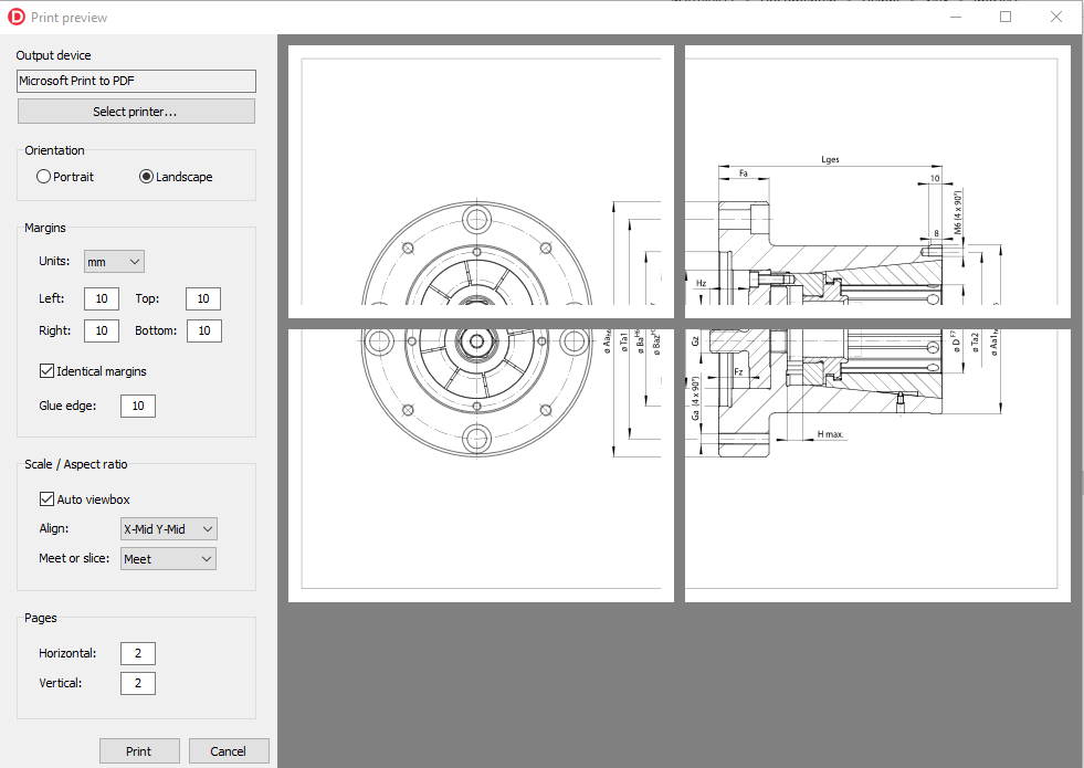
  • Property “AutoViewbox” on the TSVG2Image is set to “True”, so the width and height of the outer SVG will be automatically set to 100%
  • Property “AspectRatioAlign” will be set to “arXMidYMid” to preserve the aspect ratio of the SVG image and center it within the viewPort.
  • Property “AspectRatioMeetOrSlice” can either be “Meet” or “Slice”
  • Event “OnAfterParse” on TSVGImage will be used to read the “viewBox” attribute from the outer SVG element and store it in form variable “FViewBox”. If it does not exist, we will initialize FViewBox with the size of the viewPort.
  • Event “OnDblClick” on TSVGImage will allow loading of a new SVG image
  • Events “OnMouseDown”, “OnMouseMove” and “OnMouseUp” on TSVGImage will be used to pan the SVG image. Panning will be proportional to the zoom level.
  • Event “OnMouseWheel” on the form will be used to increase or decrease the zoom on the SVG image. The focus of the zoom will be the position of the mouse pointer on the SVG image.

So after creating the application project and setting the properties on the form and the TSVG2Image we need to implement the event handlers.

OnAfterParse

After parsing the SVG xml file an in-memory node tree data structure will be available for us to read and modify SVG elements attributes.

We can access the element nodes through the TSVG2Image “SVGRoot” property.

The “SVG” property of SVGRoot will point to the outer SVG element of the SVG image.

In the code below, we assign the viewBox attribute value to the form variable FViewBox. If no viewBox is defined on the outer SVG we initialize FViewBox with the size of the viewPort.

procedure TForm1.SVG2Image1AfterParse(Sender: TObject);
var
  SVG: ISVG;
  CR: TRect;
begin
  if not assigned(SVG2Image1.SVGRoot) then
    Exit;

  SVG := SVG2Image1.SVGRoot.SVG;

  if not assigned(SVG) then
    Exit;

  if SVG.ViewBox.IsUndefined then
  begin
    // No viewBox so we will create one with the same size as the viewPort.
    // The viewPort is defined by the dimensions of the outer SVG element.

    CR := SVG2Image1.ClientRect;

    FViewBox := SVG2Image1.SVGRoot.CalcIntrinsicSize(SVGRect(0, 0, CR.Width, CR.Height));
  end else
    FViewBox := SVG.ViewBox;
end;

Utility functions

The basis for all calculations in the application is the conversion from Mouse point to ViewBox point. The formula for this depends on the preserveAspectRatio settings. If you choose an other setting than xMidYMid the calculations will be different.

CalcZoomFactor

First we create a function to calculate the current zoom factor.

Depending on the preserveAspectRatio setting “Meet” or “Slice” and the aspect ratios of the viewBox or the viewPort, the zoom factor is calculated from the width or height ratio between the viewBox and the viewPort.

function TForm1.CalcZoomFactor: TSVGFloat;
var
  ViewPort: TRect;
  ViewPortRatioXY,
  ViewBoxRatioXY: TSVGFloat;
begin
  // This calculates the zoom factor between between the viewPort and the viewBox

  ViewPort := SVG2Image1.ClientRect;

  // We have to take into consideration the aspect ratio settings

  ViewPortRatioXY := ViewPort.Width / ViewPort.Height;
  ViewBoxRatioXY := FViewBox.Width / FViewBox.Height;

  if SVG2Image1.AspectRatioMeetOrSlice = arSlice then
  begin

    if ViewPortRatioXY > ViewBoxRatioXY then
      Result := FViewBox.Width / ViewPort.Width
    else
      Result := FViewBox.Height / ViewPort.Height;

  end else begin

    if ViewPortRatioXY > ViewBoxRatioXY then
      Result := FViewBox.Height / ViewPort.Height
    else
      Result := FViewBox.Width / ViewPort.Width;

  end;
end;

CalcViewBoxPt

Next we can create a function to calculate a viewBox point from a mouse point. This calculation is based on the xMidYMid setting.

So basically we calculate the distance of the mousepoint to the middle of the viewPort. Multiply this by the zoom factor to convert it to viewBox coordinates and then subtract it from the middle of the viewBox and finally add the top left point of the viewBox.

function TForm1.CalcViewBoxPt(const aMousePt: TPoint): TSVGPoint;
var
  ViewPort: TRect;
  Zoom: TSVGFloat;
begin
  ViewPort := SVG2Image1.ClientRect;

  Zoom := CalcZoomFactor;

  // Convert mousepoint to viewboxpoint

  Result.X := FViewBox.Left + FViewBox.Width/2 - (ViewPort.Width/2 - aMousePt.X) * Zoom;
  Result.Y := FViewBox.Top + FViewBox.Height/2 - (ViewPort.Height/2 - aMousePt.Y) * Zoom;
end;

SVGRepaint

With the SVGRepaint procedure we set the modified form variable FViewBox on the outer SVG element and force a repaint of the TSVG2Image.

procedure TForm1.SVGRepaint;
var
  SVG: ISVG;
begin
  // Get the outer SVG element

  if not assigned(SVG2Image1.SVGRoot) then
    Exit;

  SVG := SVG2Image1.SVGRoot.SVG;

  if not assigned(SVG) then
    Exit;

  // Set the viewBox attribute on the outer SVG element

  SVG.ViewBox := FViewBox;
  SVG2Image1.Repaint;
end;

Now we are ready to implement the event handlers.

OnMouseDown

On the OnMouseDown event we start panning if the left mouse button is pressed and it is not a double click.

procedure TForm1.SVG2Image1MouseDown(Sender: TObject; Button: TMouseButton;
  Shift: TShiftState; X, Y: Integer);
begin
  if (mbLeft = Button) and not(ssDouble in Shift) then
  begin
    // Save the mousedown point on mousedown

    FMouseDown := True;
    FMousePt := Point(X, Y);
  end;
end;

OnMouseMove

If we move the mouse we want to display the viewBox coordinates corresponding with the mouse pointer on the form caption.

If we are panning (FMouseDown = True) we calculate the new viewBox position from the delta mouse position.

procedure TForm1.SVG2Image1MouseMove(Sender: TObject; Shift: TShiftState; X,
  Y: Integer);
var
  Delta: TPoint;
  ViewPort: TRect;
  Zoom: TSVGFLoat;
  ViewBoxPt: TSVGPoint;
begin
  // Convert the mouse coords to viewBox coords and display in caption
  // Move the viewBox if the mouse btn is pressed

  ViewBoxPt := CalcViewBoxPt(Point(X, Y));
  Caption := Format('ViewBox Pt: %3.1f %3.1f', [ViewBoxPt.X, ViewBoxPt.Y]);

  if FMouseDown then
  begin
    // Compensate the mousemovent with the zoom factor so the image moves at
    // the same rate as the mouse

    ViewPort := SVG2Image1.ClientRect;

    Zoom := CalcZoomFactor;

    Delta := Point(FMousePt.X - X, FMousePt.Y - Y);

    // Calculate the new viewport position.

    FViewBox.Left := FViewBox.Left + Delta.X * Zoom;
    FViewBox.Right := FViewBox.Right + Delta.X * Zoom;
    FViewBox.Top := FViewBox.Top + Delta.Y * Zoom;
    FViewBox.Bottom := FViewBox.Bottom + Delta.Y * Zoom;

    // Save the new mousedown position

    FMousePt := Point(X, Y);

    // Set the new viewBox and repaint the SVG image.

    SVGRepaint;
  end;
end;

OnMouseUp

On the mouseup event we reset the form variables that control panning.

procedure TForm1.SVG2Image1MouseUp(Sender: TObject; Button: TMouseButton;
  Shift: TShiftState; X, Y: Integer);
begin
  FMousePt := Point(0, 0);
  FMouseDown := False;
end

OnMouseWheel

On every change of the mousewheel we increase or decrease the zoom level with a constant factor F.

  // Zoom with arbitrary factor

  Sign := WheelDelta / abs(WheelDelta);
  F := -Sign * 0.05;

So for zooming in and out we simply increase the width and height of the viewBox with this factor.

FViewBox.Width = FViewBox.Width * (1 + F)
FViewBox.Height = FViewBox.Height * (1 + F)

The challenge now is to focus the zoom onto the current mousepointer. This means that we want the viewBox point under the mousepointer to remain the same after changing the zoom level. For this we need to move the viewBox a bit after zooming. This is what we now have to calculate.

The viewBox points can be calculated from the mousepoint, in case of xMidYMid we have the following formula’s:


X = ViewBox.Left + ViewBox.Width/2 + (MouseX - ViewPort.Width/2) * Zoom
Y = ViewBox.Top + ViewBox.Height/2 + (MouseY - ViewPort.Height/2) * Zoom

After changing the zoom with a factor F, the formula’s can be written as follows:

X = NewViewBox.Left + ViewBox.Width/2 * (1 + F) + (MouseX - ViewPort.Width/2) * Zoom * (1 + F)
Y = NewViewBox.Top + ViewBox.Height/2 * (1 + F) + (MouseY - ViewPort.Height/2) * Zoom * (1 + F)

Because X and Y must remain the same before and after changing the zoom level, we can now calculate the values of NewViewBox.Left and NewViewBox.Top.

NewViewBox.Left = ViewBox.Left - ViewBox.Width/2 * F - (MouseX - ViewPort.Width/2) * Zoom * F
NewViewBox.Top = ViewBox.Top - ViewBox.Height/2 * F - (MouseY - ViewPort.Height/2) * Zoom * F

So the complete MouseWheel event handler looks like this:

procedure TForm1.FormMouseWheel(Sender: TObject; Shift: TShiftState;
  WheelDelta: Integer; MousePos: TPoint; var Handled: Boolean);
var
  P: TPoint;
  F: TSVGFloat;
  Sign: TSVGFloat;
  ViewPort: TRect;
  ViewBoxOriginal: TSVGRect;
  Zoom: TSVGFloat;
begin
  // Zoom the SVG in or out on every change of the mousewheel

  if WheelDelta = 0 then
    Exit;

  // Zoom with arbitrary factor

  Sign := WheelDelta / abs(WheelDelta);
  F := -Sign * 0.05;

  ViewBoxOriginal := FViewBox;

  ViewPort := SVG2Image1.ClientRect;

  Zoom := CalcZoomFactor;

  P := SVG2Image1.ScreenToClient(MousePos);

  FViewBox.Left := ViewBoxOriginal.Left - ViewBoxOriginal.Width/2 * F 
    - (P.X - ViewPort.Width/2) * Zoom * F;

  FViewBox.Top := ViewBoxOriginal.Top - ViewBoxOriginal.Height/2 * F 
    - (P.Y - ViewPort.Height/2) * Zoom * F;

  FViewBox.Right := FViewBox.Left + ViewBoxOriginal.Width * (1 + F);
  FViewBox.Bottom := FViewBox.Top + ViewBoxOriginal.Height * (1 + F);

  SVGRepaint;
end;


OnDblClick

Finally we create an even handler for loading an SVG file into the TSVG2Image control.

procedure TForm1.SVG2Image1DblClick(Sender: TObject);
begin
  // Load a new SVG image by dubbel clicking the TSVG2Image

  if OpenDialog1.Execute then
  begin
    // Clear any SVG present in the SVG stringlist property, because it has
    // priority over the SVG filename property

    SVG2Image1.SVG.Clear;

    FViewBox := TSVGRect.CreateUndefined;

    SVG2Image1.Filename := OpenDialog1.FileName;
  end;
end;

The complete source code of this example project can be found here.

Warping SVG paths

It seems it is 27 years already since Delphi Pascal was created. I can say that I have used it from the start, even before that, when I was at University we learned programming with Turbo Pascal. Today, if I want to flesh out some idea’s I have, Delphi is still the tool I grab first.

One idea I had recently, is how I could recreate the effects in SVG of another tool that has been around for many years, namely “WordArt”. With this you can apply all kinds of effects on pieces of text. One of them is “warping” the text, so that is what I want to try in this post.

The source code can be found here. You will need the (demo) SVG control package for compilation. You could also use this code with some alterations in Delphi FMX (Firemonkey), because basically it works on a TPathData object.

With “Warping” I mean, distorting a 2d rectangular space into another shape using a warp-function. The picture below shows the warping functions that you could select in WordArt97.

For example, to warp a rectangle to the shape shown in the left bottom, this would involve a tapering from left to right.

I find it easier to first “normalize” the rectangle that you start out with, so after normalization the left top is point (0,0) and the right bottom is (1,1).

Nx = (P.X – Rect.Left) / Rect.Width

Ny = (P.Y – Rect.Top) / Rect.Height

Now we can use Nx and Ny as interpolation parameters.

The tapering is an interpolation function of Nx, so if we start out with a height of 100% and want to end with a height of 30%, we interpolate from 1.0 to 0.3:

Scale = 1.0 + (0.3 – 1.0) * N.x

So the warp function becomes

Wx = Nx

Wy = Ny * Scale + (1.0 – Scale) / 2

Finally we de-normalize so we scale back to the dimensions of the original rectangle:

X = Rect.Left + Rect.Width * Wx

Y = Rect.Top + Rect.Height * Wy

On the other hand, the left bottom shape could also be a perspective projection. This can be written, for example, as follows (maybe experiment a bit with the constants to get the right fit):

Scale = 0.5 * (1.5 + N.X)

Wx = 0.5 + (N.X – 0.5) / Scale

Wy = 0.5 + (N.Y – 0.5) / Scale

For the image at the start of the post I use a slightly more complex function. The points are defined by an arc in the x direction that has a large radius at the top and a smaller one at the bottom. Also the image is tapered to the top. You can find this function in the source code.

So now for the rest of the code.

Text to path

I start of with the following SVG. So I have downloaded the font “Ranchers” for the text. I have placed this font in the same directory as this SVG so the renderer can find it. The font is included in the SVG by the CSS in the style element and then applied by the “font-family” attribute on the text element.

<?xml version="1.0" standalone="no"?>

<svg width="10cm" height="10cm" viewBox="0 0 1000 1000"
     xmlns="http://www.w3.org/2000/svg" version="1.1">  
  
  <style type="text/css"><![CDATA[

    @font-face {
		font-family: "Ranchers";
		src: url("Ranchers-Regular.ttf") format("ttf");
	}		
	
  ]]></style>

  <g id="warp">
  
  
    <text font-family="Ranchers">
	  <tspan font-size="260" text-anchor="middle" x="500" y="400">27</tspan>
	  <tspan font-size="120" text-anchor="middle" x="500" y="510">years of</tspan>
	  <tspan font-size="260" text-anchor="middle" x="500" y="770">Delphi</tspan>
	</text>	
  	
	<path d="M100,100 L900,100 L900,900 L100,900 Z" fill="none" stroke="green"/>
  </g>
  
  <rect x="0" y="0" width="1000" height="1000" fill="none" stroke="black" />

</svg>

The next thing that has to be done is converting the text elements to path elements. In the SVG control package you can do that by adding [sroTextToPath] to the “RenderOptions” property of, for example, the TSVG2Image. On rendering the SVG, any text element will be converted to paths, a path for every glyph. The SVG will be transformed to something like below (this is not the complete SVG):

<?xml version="1.0" standalone="no"?>
<svg width="10cm" height="10cm" viewBox="0 0 1000 1000" xmlns="http://www.w3.org/2000/svg" version="1.1">
  <style type="text/css">
    <![CDATA[

    @font-face {
		font-family: "Ranchers";
		src: url("Ranchers-Regular.ttf") format("ttf");
	}		
	
  ]]>
  </style>
  <g id="warp">
    <g id="" font-family="Ranchers">
      <g id="" font-size="260" text-anchor="middle">
        <path d="M121.420,-159.900 ... 121.420,-159.900Z" transform="matrix(1,0,0,1,372.896003186703,400)" />
        <path d="M9.100,0.000L79.300 ... 66.820,0.000Z" transform="matrix(1,0,0,1,498.996001660824,400)" />
      </g>
      <path d="" transform="matrix(1,0,0,1,625.615996778011,400)" />
	  
  ...

In Delphi FMX you could use the ConvertToPath method of TTextlayout to convert a piece of text to a TPathData object.

Iterating over path sections

Next we need to iterate over the sections of every path. For this we must convert de “d” attribute of the path, which contains the path commands as text, to a path point list. In Delphi FMX you can do that by setting the “Data” property of the TPathData object. In the SVG package this works basically the same (see source code).

The end result is a list of path points that define the segments of the path. There are basically only two sort of segments, straight lines or cubic beziers.

Interpolating path segments

For a smooth result, it might not be enough to just transform the points in the path point list using the warp function. So what we can do is split the segments until they fit into the warped space within a certain accuracy.

For a straight line, this can be done like this:

  1. Calculate the middle point of the line P0, P1: M
  2. Transform this point using the warp function: Mw
  3. Warp the start and end point of the line: P0w, P1w
  4. Calculate the midpoint of the line P0w, P1w: M2
  5. If the distance between Mw and M2 is greater than some error, we split the original line P0, P1 into two new lines: P0, M and M, P1 and we repeat the process for each of these two lines
  6. Otherwise we have reached the accuracy we need and we can add the warped line to the result path point list.

The same can be done with the cubic bezier.

Finally we can convert the path point list back to a path command string and assign it to the “d” attribute of the path.

So that is basically it. You can find the source code for warping paths on the delphi-svg-control-examples git hub page.

Rendering SVG to a command list or printer

From version 2.40 update 8 onwards, the SVG control package supports rendering to a command list or printer in case of render context GDI+ as well as render context Direct2D.

In this post I will show a couple of examples how this can be used.

Rendering to a command list

A command file is basically a recording of graphical commands that, if played back, result in an image. It is in that respect similar to an SVG file, only it is bound to a specific graphical platform.

The EMF file for the Windows GDI+ platform, also refered to as a metafile, is an example of a command list. But Direct2D also supports a commandlist through the ID2D1CommandList interface (defined in D2D1_1.h).

(Note that the ID2D1CommandList is supported by the Direct2D 3D11 render context not the Direct2D WIC render context.)

The nice thing about a command list, is that it can be used as an (vector) image, so just like an SVG, it can be scaled without quality loss.

In the SVG control package we use interfaces to expose functionality that is independent of the underlying graphical platform. For the command list, the following interface is defined:

var
  CmdList: ISVGRenderContextCmdList;
  ...
CmdList := TSVGRenderContextManager.CreateCmdList;

To record commands in the command list in the “SVG control package”, we need to create a rendercontext based on the commandlist.

var
  Context: ISVGRenderContext;
  ...
Context := TSVGRenderContextManager.CreateRenderContextCmdList(CmdList, 50, 50);

In this example the “width” and “height” of the context is 50 and 50. We can now use the drawing commands on the rendercontext and these will in turn be recorded in the command list. In the example below all the commands needed to render an SVG image are recorded into the command list:

var
  Root: ISVGRoot;
  CmdList: ISVGRenderContextCmdList;
  Bitmap: TBitmap;
  Context: ISVGRenderContext;
  i, j: Integer;
...
  // Render an SVG to a command list

  // Create a root object
  Root := TSVGRootVCL.Create;

  // Load an SVG image in the root object
  if Root.DocFindOrLoad(TSVGIri.Create(isFile, aFilename, '')) = nil then
    raise Exception.CreateFmt('Loading %s failed', [aFilename]);

  // Create a command list to record graphical commands
  CmdList := TSVGRenderContextManager.CreateCmdList;

  // Create a rendercontext for the command list of size 50, 50
  Context := TSVGRenderContextManager.CreateRenderContextCmdList(CmdList, 50, 50);

  Context.BeginScene;
  try
    // Use the build-in function "SVGRenderToRenderContext" to render 
    // the SVG contained in the root object to the command list 
    // via the rendercontext
	
    SVGRenderToRenderContext(Root, Context, 50, 50);
  finally
    Context.EndScene;
  end;

Now the “CmdList” object contains all the graphical commands necessary to render the SVG image on a specific platform, which can be GDI+ or Direct2D 3D11, depending on the global render context settings.

One use for a command list is to render the image as a pattern. The example below renders the SVG recorded in the commandlist as a pattern on a bitmap.

  // Create a bitmap
  FBitmap := TSVGRenderContextManager.CreateCompatibleBitmap(350, 200, True);

  // Create a rendercontext for the bitmap
  Context := TSVGRenderContextManager.CreateRenderContextBitmap(FBitmap);

  // Draw the command list as a pattern on a bitmap
  Context.BeginScene;
  try
    for i := 0 to 3 do
      for j := 0 to 6 do
      begin
        Context.DrawCmdList(CmdList, SVGRect(i*50, j*50, (i+1)*50, (j+1)* 50));
      end;
  finally
    Context.EndScene;
  end;  

Rendering to a printer

Just as for the command list, the SVG control package also has a number of interfaces and functions defined for rendering to a printer, independent of the underlying graphical platform.

Rendering to a printer is supported by render context GDI+, Direct2D 3D11, Quartz and FMX canvas.

First of all, a print job must be created. This can be done using function “CreatePrintJob” of the render context manager.

var
  PrintJob: ISVGPrintJob;
  ..
PrintJob := TSVGRenderContextManager.CreatePrintJob('PrintSVG');

Using the “PrintJob” interface we can create pages to render to.

var
  Context: ISVGRenderContext;
  ..
Context := PrintJob.BeginPage(Printer.PageWidth, Printer.PageHeight);

If we are finished with drawing to the rendercontext we must call “EndPage” on the PrintJob interface, at which point the page is sent to the printer.

PrintJob.EndPage;

In the example below, a number of SVG’s that are contained in a stringlist are each printed on a page.

var
  i: Integer;
  Root: ISVGRoot;
  PrintJob: ISVGPrintJob;
  Context: ISVGRenderContext;
begin
  // Select a printer
  if not PrintDialog1.Execute then
    Exit;

  // Create a root object
  Root := TSVGRootVCL.Create;

  // Create a print job
  PrintJob := TSVGRenderContextManager.CreatePrintJob('PrintSVG');

  for i := 0 to sl.Count - 1 do
  begin

    // Load the SVG in the root
    if Root.DocFindOrLoad(TSVGIri.Create(isFile, sl[i], '')) = nil then
      raise Exception.CreateFmt('Loading %s failed', [sl[i]]);

    // Render to page
    Context := PrintJob.BeginPage(Printer.PageWidth, Printer.PageHeight);
    try
      Context.BeginScene;
      try
        SVGRenderToRenderContext(
          Root,
          Context,
          Printer.PageWidth,
          Printer.PageHeight,
          [sroClippath, sroFilters],
          True // scale to page
          );

      finally
        Context.EndScene;
      end;

    finally
      PrintJob.EndPage;
    end;
  end;
end;

An implementation for rendering SVG to a printer: “PrintPreview”, can be found on the delphi-svg-control-examples github page.

The picture at the start of this post shows a screenshot of the SVG print preview, which has several settings for defining the layout of the SVG on a page. For example, you can set margins and the scaling and alignment.

In can also print one SVG over several pages, in which case you can define a “glue edge”, so you can glue the pages together after printing.

The print preview example can be compiled with the full SVG control package update 8 or later and the latest versions of the SVG control demo package.

Render animated SVG to GIF, AVI or APNG

This example Delphi application demonstrates how to render an animated SVG to a GIF, AVI or animated PNG.

The application makes use of the following libraries:

For the SVG it uses the SVG control package or the demo version of the package.

For the animated PNG, the imaginglib by Marek Mauder

For the AVI, CreateAviFromBitmap by Francois Piette

For GIF, no external library is needed because it is part of the Delphi VCL.

The source code of the application can be found on delphi-svg-control-examples.

The SVG used in this example is “Steam engine slide-valve cylinder animation“.

Application layout

On the top left of the application form there is a TValueListEditor control where you can set the SVG input file, width en height and some other settings.

On the bottom left there is a TTabControl with another TValueListEditor where you can select the output format and some settings for the output.

Then on the top you can specify the “duration” for the animation in milliseconds and the “frames per second”.

The “duration” is something you have to find out yourself by inspecting the SVG file. SVG animations can be very complex, because parts of the animation can be triggered by events. In simple cases you can figure out the duration by looking at the “dur” attributes in the SVG.

For CSS animations, you look for the “animation-duration” property or the short hand version “animation“, which has several animation properties rolled into one property.

Of course, increasing the “frames per second” will result in a smoother animation but a larger output file.

The center pane of the application will display a preview of each frame while it is recorded. You start the recording with the button “Record”.

At the end of the recording, the application will save the output file to the file specified in the output settings.

Stepping through the SVG animation

For stepping through the SVG animation I have created a class TSVGFrameRenderer. Because we do not have to display the SVG animation in real time, the animation timer is not needed.

The total number of frames is calculated by:

FrameCount := Duration * FPS div 1000;

Where FPS is the “Frames per second”.

And the time in milliseconds between each frame is:

DeltaTime :=  1000 div FPS;

The input for the frame renderer is a “SVG root object”, specified by the interface ISVGRoot. The root object contains the parsed SVG file.

The root object also implements interface ISVGAnimationTimerTarget. This interface can be used to step through the SVG animation, for example:

var
  Target: ISVGAnimationTimerTarget;

...

// Get the animation target interface

if not Supports(SVGRoot, ISVGAnimationTimerTarget, Target) then
  Exit;

...

// Start the animation

Target.DoAnimationTimerStart;

...

// Advance the animation "Delay" milliseconds

Target.DoAnimationAdvanceFrame(Delay);

The frame render will render the SVG to a bitmap on each step.

The full code of the frame renderer can be found here.

Rendering to an animated PNG

For rendering the animated PNG we use the imaginglib by Marek Mauder. This is a library for reading, writing and converting many different image formats.

At the moment we use only one output parameter for the PNG animation: “AnimationLoops”. This specifies how many times the animation will repeat itself. A value of 0 means endless repetition.

procedure TSVGConvTargetApng.Convert(aFrameRenderer: TSVGFrameRenderer);
var
  DataArray: TDynImageDataArray;
  Meta: TMetadata;
  Format: TPNGFileFormat;
  Index: Integer;
begin
  // https://github.com/galfar/imaginglib

  SetLength(DataArray, 0);
  try
    if aFrameRenderer.RenderFirst then
    begin

      // Create an array to store the frame images

      SetLength(DataArray, aFrameRenderer.StepCount);

      try
        repeat

          // Convert the bitmap from the frame rendere to an image
          // and store it in the array

          ConvertBitmapToData(aFrameRenderer.Bitmap, DataArray[aFrameRenderer.Step]);

        until not aFrameRenderer.RenderNext;

      finally
        aFrameRenderer.RenderClose;
      end;
    end;

    // Create a meta object for PNG settings

    Meta := TMetadata.Create;
    try
      // Set "AnimationLoops" in the meta object

      Meta.SetMetaItemForSaving(SMetaAnimationLoops, AnimatedLoops);

      // Set the frame delay on each image

      for Index := 0 to Length(DataArray) - 1 do
        Meta.SetMetaItemForSaving(SMetaFrameDelay, 1000 / aFrameRenderer.FPS, Index);

      // Save the array to file in animated PNG format

      Format := TPNGFileFormat.Create(Meta);
      try
        Format.SaveToFile(FileName, DataArray);
      finally
        Format.Free;
      end;

    finally
      Meta.Free;
    end;

  finally
    FreeImagesInArray(DataArray);
  end;
end;

The resulting animated PNG looks like this (will only animate if your browser supports animated PNG).

The imaginglib doesn’t have components for displaying an animated PNG in Delphi (or Freepascal). Below is a very simplistic way to display the animated PNG based on a timer:

uses
  ...
  Imaging,
  ImagingComponents,
  ImagingNetworkGraphics
  ...

TForm1 = class(TForm)
...
  private
    FFrame: Integer;
    FDynImageDataArray: TDynImageDataArray;
  public
    procedure LoadPng(const aFilename: string);
...

procedure TForm1.FormCreate(Sender: TObject);
begin
  SetLength(FDynImageDataArray, 0);
  FFrame := 0;
end;

procedure TForm1.FormDestroy(Sender: TObject);
begin
  Finalize(FDynImageDataArray);
end;

procedure TForm1.LoadPng(const aFilename: string);
var
  PngFormat: TPNGFileFormat;
  DelayVar: Variant;
begin
  PngFormat := TPNGFileFormat.Create(nil);
  try
    // Load PNG in image array

    PngFormat.LoadFromFile(OpenDialog1.Filename, FDynImageDataArray);

    // Get delay from global meta

    DelayVar := GlobalMetadata.MetaItems[SMetaFrameDelay];
    if not VarIsNull(DelayVar) then
      Timer1.Interval := DelayVar;
  finally
    PngFormat.Free;
  end;

  // Start timer

  FFrame := 0;
  Timer1.Enabled := True;
end;

procedure TForm1.PaintBox1Paint(Sender: TObject);
var
  Bitmap: TBitmap;
begin
  if FFrame < Length(FDynImageDataArray) then
  begin
    Bitmap := TBitmap.Create;
    try
      ConvertDataToBitmap(FDynImageDataArray[FFrame], Bitmap);
      PaintBox1.Canvas.Draw(0, 0, Bitmap);
    finally
      Bitmap.Free;
    end;
  end;
end;

procedure TForm1.Timer1Timer(Sender: TObject);
begin
  PaintBox1.Repaint;

  if FFrame < Length(FDynImageDataArray) - 1 then
    Inc(FFrame)
  else
    FFrame := 0;
end;

Rendering to GIF

In this example we use the GIF functionality that is part of the Delphi VCL, but you could also use the imaginglib by Marek Mauder for this. I based the example below on the GIF animation demo on Andeas Melander’s website. The Gif also takes a parameter “AnimationLoops” for a finite or endless repetition. Also some other parameters which are explained in the Delphi help or on Andreas website.

procedure TSVGConvTargetGif.Convert(aFrameRenderer: TSVGFrameRenderer);
var
  GIFImage: TGifImage;
  GifFrame: TGIFFrame;
  GCE: TGIFGraphicControlExtension;
  LoopExt: TGIFAppExtNSLoop;
begin
  GIFImage := TGifImage.Create;
  try
    if aFrameRenderer.RenderFirst then
    begin
      try
        repeat
          // Add the bitmap to the gif image list

          GifFrame := GifImage.Add(aFrameRenderer.Bitmap);

          // Loop extension must be the first extension in the first frame

          if GifImage.Images.Count = 1 then
          begin
            LoopExt := TGIFAppExtNSLoop.Create(GifFrame);

            // Number of loops (0 = forever)

            LoopExt.Loops := AnimatedLoops;
          end;

          // Add Graphic Control Extension

          GCE := TGIFGraphicControlExtension.Create(GifFrame);

          // Delay is in hundreds of a second

          GCE.Delay := aFrameRenderer.Delay div 10;
          if Transparent then
          begin
            GCE.Transparent := True;
            GCE.TransparentColorIndex :=  GifFrame.Pixels[0, aFrameRenderer.Height - 1];
            GCE.Disposal := dmBackground;
          end;

        until not aFrameRenderer.RenderNext;

      finally
        aFrameRenderer.RenderClose;
      end;
    end;

    // Optimize Color map...

    if OptimizeColorMap then
      GifImage.OptimizeColorMap;

    // Optimize aGifImage frames...

    if OptimizeOptions <> [] then
      GifImage.Optimize(OptimizeOptions, rmNone, dmNearest, 0);

    if not GifImage.Empty then
      GifImage.SaveToFile(Filename);

  finally
    GifImage.Free;
  end;
end;

The GIF format is older technology. It doesn’t support transparency by alpha channel as the PNG format does. On the other hand, it is widely supported. You can sort of simulate transparency by setting the background colour of the SVG. Choose a colour that is not present in the SVG itself. Then set the output parameter “Transparent” to True. The resulting GIF looks like this:

Rendering to AVI

For rendering to AVI, we use the library CreateAviFromBitmap by Francois Piette. The only output setting for the AVI is a compression setting: “None” or “XVID”. “XVID” will only work if you have installed the necessary codec, as explained by Francois on his website.

The code for rendering to AVI is very simple:

rocedure TSVGConvTargetAvi.Convert(aFrameRenderer: TSVGFrameRenderer);
var
  Avi: TAviFromBitmaps;
  CompressionTag: FOURCC;
begin
  // http://francois-piette.blogspot.com/2013/07/creating-avi-file-from-bitmaps-using.html

  // Compression will only work if you have installed the necessary codecs
  // XVID compressor, download the setup from http://www.xvid.org

  CompressionTag := MKFOURCC('D', 'I', 'B', ' ');

  case Compression of
    acXVID: CompressionTag := MKFOURCC('x', 'v', 'i', 'd');
  end;


  Avi := TAviFromBitmaps.CreateAviFile(
    nil,
    Filename,
    CompressionTag,
    Cardinal(aFrameRenderer.FPS),
    1);
  try

    if aFrameRenderer.RenderFirst then
    begin
      try
        repeat
          // Add the bitmap to the avi

          Avi.AppendNewFrame(aFrameRenderer.Bitmap.Handle);

        until not aFrameRenderer.RenderNext;

      finally
        aFrameRenderer.RenderClose;
      end;
    end;

  finally
    Avi.Free;
  end;
end;

Rendering an animated SVG to PNG, GIF or AVI and then using these in your application has the advantage that these later formats do not use as much computing power as an animated might SVG might need.

Simple SVG animations are usually not a problem, but In SVG you can animate almost every attribute, also for example attributes on filters. Rendering SVG filters can be very expensive in terms of computing power, so it might not be possible to render frames fast enough for a smooth animation.

Also you might be less depended on specific fonts or other resources that are needed on the host computer for rendering the SVG.

On the other hand, the SVG file is much smaller. In this example the PNG file is 602KB, the AVI (uncompressed) is 17583KB and the GIF is 492KB. The SVG file is only 13KB.

SVG control package v2.4

In version 2.4 of the SVG control package the following functionality is added:

  • Support for SVG and CSS animation using SMIL
  • Converting “text” elements to “path” elements
  • Support for different XML vendor implementations

Support for SVG and CSS animation using SMIL

SVG can be added to SVG images by the “animate”, “set”, “animateMotion” and “animateTransform” elements. In CSS animation can be defined by “animate…” properties and the style rule “@keyframes”. SMIL is used to synchronize the animation of SVG animated elements and CSS animations.

Depending on the complexity of the SVG image, animating SVG may require a lot of computing power. Especially if pixelwise operations are included in the animation, for example clippaths, masks and filters. To reduce the load on the system and therefore enable a higher frame rate, some optimizations where added to version 2.4:

  • A caching system was added to the rendering system, so some values that where calculated in a previous frame can be used in the next.
  • SVG is a tree structure, in many animated SVG images, not all branches of the SVG image contain animations. So these branches are static an can be rendered to a bitmap buffer and don’t have to be rerendered every frame. This functionality is controlled by the rendering option [sroPersistentBuffers]
  • For VCL and Freepascal a new control, TSVG2WinControl, was added. This control does not support transparency and therefore the SVG image does not have to be blended with the background on every frame. In combination with render context “SVGDirect2d3D11”, this control will use a DirectX swap chain and can make more use of the GPU.

For controlling animations a new component, TSVG2AnimationTimer, was added to the package. This component starts/stops or paused/un-pauses animations and calculates framerates. One or more of the SVG controls can link to this component.

A more detailed description of the animation functionality can be found in the online help.

Below is a demonstration of some SVG animations that are animated with the SVG control package v2.4.

The following SVG images are used in the demo:

Converting “text” elements to “path” elements

For rendering text, fonts are needed and these have to be available on the system where the SVG is rendered. If this is not the case, the renderer will use a default font, which means that the SVG image is not exactly rendered as how it was intended.

One way around this, is to embed an SVG font in the SVG file.

Another way which is now available in v2.4, is to convert text to paths. The way to do this involves the following steps:

  • Render an SVG image with render option [sroTextToPath]
  • Make a copy of the SVG root object
  • Save the XML strings of SVG XML document of the copied SVG Root object

Details of this functionality can be found in the online help.

Support for different XML vendor implementations

In Delphi TXMLDocument is used as a wrapper for vendor specific DOM implementations. In version 2.4 of the package, TXMLDocument and TXMLNode are used as the base classes for the “rendering tree”. The DOM implementation on the other hand, represents the “document tree”.

So now different vendors can be used for parsing the document tree, if this is required. The SVG control package also has a DOM implementation available that is used by default, that has vendor name “SVG control DOM”.

TXMLNode can also represent attributes, however, because this makes parsing SVG very slow, this is suppressed. The package makes use of its own implementation of SVG attributes, also because these have special requirements for interpolation of values for animation.

Because of the large number of changes it was decided to create a new version of the package, but version 2.4 is available for all license holders of version 2.3 with no extra cost.

If you don’t have a license you can try out the demo packages, these are without the source code and only for Windows 32bit, but fully functional.

SVG control package v2.3 update 9

This update contains bug fixes and some functional changes to the SVG image list and the SVG controls.

Changes to the SVG image list

The rows in the grid can now be moved to change the order of SVG images.

The following bugs in the image list editor are fixed:

  • There was a problem that the images of any connected “Linked SVG image lists” where lost after making changes to the parent image list, and had to be manually recreated.
  • The “Scaled” property setting was lost after pressing “Cancel” on the SVG image list editor.

Changes to TSVG2Control and TSVG2Image

These controls are used to host a single SVG image.

The SVG image that is hosted can be specified by reference, in that case you would use the “Filename” property and you would supply the SVG files separately with your application. Or the SVG image can be loaded in the “SVG” (TStrings) property, in that case the SVG image is stored in the form file and will be part of the executable of your application.

The Delphi IDE sets a limit on the number of lines you can load in a TStrings property at design time. It this update a component editor is added to these controls, to allow loading of large SVG images.

The SVG data will be stored in the form file and in the executable. Another change is that this SVG data will now be compressed to save space.

Other bug fixes

  • To support mousepointer events, the SVG rendering engine can calculate the bounds of visual elements, paths, rectangles etc. When the parent form or control contains a transform on the canvas, these calculated bounds where not always correct, which resulted in mousepointer events not being fired.
  • When both GDI+ and Direct2D render contexts are enabled, the resulting application would not start on a Windows system that does not support DirectX. This would be Windows XP for example. This is fixed by adding “delayed” to the external procedures targeting DirectX.

Future updates

A new version of the package, v2.4 is in progress and will be available in a couple of weeks. This version of the package will add CSS animation and SMIL animation functionality among other things.

Because of the large number of changes needed to support animation, the package version will increase to allow a controlled transition from version 2.3 to version 2.4.

However, I would like to mention here that v2.4 will be available to all v2.3 license holders without extra costs, when this version comes available.

New functionality for SVG image list

In update 4 of the package, new functionality is added to the SVG image list to increase the number of images that can be created and also more options for exporting and linking to controls.

The SVG image list extends the functionality of the normal TImageList, in that it can automatically create all the images needed out of a list of scalable vector graphics.

Nowadays applications must be able to support monitor DPI scaling, so images are needed in multiple resolutions and also, images are needed that reflect a state, for example a “disabled” state.

To support this, two dimensions are added to the SVG image list: a list of “styles” and a list of “resolutions”.

So the number of images that can now be created with an SVG image list is:

Image count = SVG count * Style count * Resolution count

In the component editor, that is shown in the image above, the SVG’s and Styles are laid out in a grid.

Resolutions

How the resolutions are managed depend for a large part on the base TImagelist for Delphi VCL, FMX or Lazarus, from which the SVG image list is derived:

  • The VCL TImageList does not itself support multiple resolutions (but in Delphi 10.3 the TVirtualImageList and TImageCollection components where added that do).
  • The FMX TImageList is introduced in Delphi XE8 and supports multiple resolutions through the multi-resolution bitmap.
  • The Lazarus TImageList supports multiple resolutions from version 1.9 and above.

The SVG image list will render all images on all resolutions that are defined on the base TImageList. For VCL the resolutions can be defined with an extra list of resolutions or rendered “on demand”. See the online help for details.

Styles

The styles are created by modifying the original SVG. For modifying the SVG’s in the SVG image list the xml feature “Entities” is used. With an entity you can replace a piece of text in the body of an xml with something else. So you could replace an attribute, for example a color or a transformation, or you could replace an element, for example replace a rectangle for a circle.

The SVG image list has two means for modifying the SVG:

  • Defining an “Outer SVG” that embeds the original SVG by using the entity &cur_svg;. This can be used to modify the original SVG as a whole, for example by applying opacity or a filter.
  • Replacing parts of the original SVG with entities. These will show up in the “Style entity list”. In the Style entity list you can specify values for each entity.

On the Style page of the SVG image list, there are some default settings for “Outer SVG” available, for example a “Saturation” filter to apply a “Disabled” look, or a “Drop shadow” effect.

The other method requires a bit more work. For this you need to edit the original SVG. The image below shows some variations on a single SVG that can be created with this method. A example how to do this can be found in the online help.

Linking to controls

The SVG image list is derived from a normal TImageList, so controls that can link to a TImageList can also link to a SVG image list.

Some components and controls have several properties that can link to an image list depending on the state of the images, for example a TActionManager has four properties: Images, DisabledImages, LargeImages and LargeDisabledImages.

So we may want to have all the SVG’s and Styles in a central place but also link to these four separate properties of the TActionmanager. This can be done by using the “SVG Linked image list” as an intermediate.

The SVG linked image list has alle the functionality of a SVG image list except that it has no SVG or Style data of its own, it gets these from the parent SVG image list it is linked to. It also has a “ParentStyleIndex” property, with this we can select a Style from the parent SVG image list.

This is a bit like the TVirtualImageList and TImageCollection of Delphi 10.3 where SVG linked image list is a TVirtualImageList and the SVG image list is the TImageCollection.

An example is shown below. This is the VCL demo viewer application, it has a central SVG image list with two styles, one for normal images and one for disabled images.

Then there are two SVG linked image lists, one, “ilNormal” selects the normal images from the SVG image list and is connected to the “Images” property of the action manager, the other “ilDisabled” is connected to the “DisabledImages” property.

Exporting images

The SVG image list has the capability to create bitmap images from SVG’s. This only happens when SVG’s are added to the list or certain properties of the image list are changed, for example the “Width” or “Height”, otherwise it just behaves as a normal image list.

So it only makes sense to use a SVG image list, if you actually need to render images in runtime, otherwise you might as well use a normal TImageList in your application, because of course, the SVG rendering software is complex and if you don’t use it in your application it is basically dead weight.

So another use of the SVG image list is just to produce images that you export and subsequently import in a normal image list. The SVG image list has a number of properties to help with this for example for naming the exported files, so you can easily import them back in bulk.

The images of the SVG image list can be exported as Bmp, Png, JPeg or SVG files. The VCL and Lazarus versions also can export multi layered Windows Icons.

Upgrading the SVG control package

If you are already using an earlier version of the SVG control package, you will get some warnings about properties that are changed or maybe are removed. All the warnings should be accepted and all should be ok, but to be on the safe side, make a backup of your code including the previous version of the SVG control package before upgrading. See the change log for details.

The SVG icons used in the examples are from: https://github.com/icons8/flat-color-icons/tree/master/svg

SVG Control Package Version 2.3

This is a complete rewrite of the package partly to remove some limitations in the previous version but also to make it ready for future improvements and extensions.

Among the changes are:

  • Support for FPC Lazarus
  • Added interfaces for more graphic libraries
  • Improved text rendering
  • Faster integrated parser
  • New licensing terms

Support for FPC Lazarus

The package will now also compile for FPC Lazarus, Windows, MacOS and Linux.

You need at least FPC 3.0.4 and Lazarus 1.8.4. Also needed is the ” rtl-generics” package.

For Delphi you need at least XE2.

Added interfaces for more graphic libraries

For Windows next to the Direct2D “WIC” render context there is also a render context based on the DirectX 11 “Device Context”. This last one supports hardware accelerated effects. You can use theses render contexts with Delphi and FPC Lazarus.

All the header files needed to render with DirectX are translated and included in the package.

For Mac OS there is a dedicated render context based on “Quartz”, can be used with Delphi FMX and FPC Lazarus.

There is now also a render context based on the “Graphics32” library

For FPC Lazarus there is a render context based on “BGRA bitmap“.

See the “Technical design” page for an overview of the available render contexts.

Or take a look at the “Rendering examples” how these render contexts compare.

Improved text rendering

Similar to the “Render context” interface, an interface is added to the package that gives access to font and text formatting libraries, called a “text layout”.

For Windows there is a text layout based on “DirectWrite” and legacy “GDI fonts” with “Uniscribe”. Again all header files needed are included in the package.

For MacOS there is a text layout based on “Core text”.

These text formatting libraries support complex text formatting, for example bi-directionality and ligatures.

There is also a text layout based on “Freetype” but this one has only limited text formatting capabilities but is available for every operating system.

The text layout is independent from the render context, so you can for example choose “Graphics32” render context and “DirectWrite” as a text layout.

See the “Technical design” page for an overview of the available text layouts or the “Rendering examples” for comparison.

Faster integrated parser

The parser is integrated, this means that you can set attributes by text, for example to change the “style” attribute for an element you can simply code it like so:

Node.Attributes['style'] := 'font-family: "times"; font-size: 24; fill: red;';

You can also add fragments to create child elements, for example:

procedure TForm1.SVG2Image1Click(Sender: TObject);
var
  Element: ISVGElement;
begin
  Element := SVG2Image1.SVGRoot.Element['text'];
  if assigned(Element) then
  begin
    Element.ChildNodes.Clear;
    Element.AddFragment('<tspan fill="yellow">Button <tspan fill="red" font-weight="bold" text-decoration="underline">clicked!</tspan></tspan>');
    SVG2Image1.Repaint;
  end;
end;

The help file contains a number of examples how to create animations or interact with SVG graphics.

New licensing terms

The new license is based on a subscription. There is a one time fee to buy the source code and a yearly subscription fee for receiving fixes and updates.

If you have a v2.2 license you can upgrade to v2.3 for the amount of the subscription fee.

For details see the “Order page“.

Or check out the free demo package or the demo viewer apps here.

Drawing outlines around SVG elements

The SVG control package offers a number of controls to display SVG graphics. But if you want more control over how SVG graphics are rendered or if you want to post process graphics, you can also use the lower level classes, interfaces and functions of the package.

Two of these interfaces are

ISVGRenderContext

and

ISVGRoot

ISVGRenderContext is a high quality canvas, very much like the Delphi Firemonkey canvas, but it has the advantage that you can use it in Delphi VCL also. It always draws to a bitmap which you have to supply.

It has most of the drawing functions that the Firemonkey canvas has. Functions like DrawCircle, DrawRect, FillRect, FillPath, ApplyFill, ApplyStroke, MultiplyMatrix BeginScene, EndScene and so on.

You can use the render context (RC) for example to add drawings before or after you render an SVG graphic, or you could just use it for high quality drawings, also supporting transparency, something Delphi VCL does not excel in.

ISVGRoot is the root of the tree of SVG elements of the SVG graphic, equivalent to the Document Object Model (DOM)  in an internet browser. This is created after parsing the SVG xml text and allows you to manipulate elements and parameters before actually rendering the graphic. You can also use it to measure element dimensions.

I’ll give an example here how you can use both to render an SVG graphic an then to post process the graphic to draw some outlines around some of the elements in the SVG graphic.

We use the following simple SVG graphic and we will draw outlines around the text, star group an rotated ellipse.

<?xml version="1.0" encoding="UTF-8" standalone="no"?>
<svg
  xmlns="http://www.w3.org/2000/svg"
  id="test_svg"
  version="1.1"
  height="320"
  width="480"
  viewBox="0 215 120 80">
  <g 
    id="layer1">
    <text
      id="txt" x="55" y="225" font-family="sans-serif" font-size="8">
      <tspan id="tspan1">A star group</tspan>
      <tspan id="tspan2" x="55" dy="1em">an ellipse</tspan>
      <tspan id="tspan3" x="55" dy="1em">and some text</tspan>
    </text>
    <ellipse
      id="ellipse" transform="rotate(25)" cx="200" cy="215" rx="25" ry="7.5" fill="#00ff00" stroke="#000000" stroke-width="0.75" />
    <g
      id="star_group">
      <path
        id="star1" fill="#ff2a2a" stroke="#000000" stroke-width="0.75"
        d="m 41.010416,262.03718 -4.104352,-0.60791 -3.016279,2.84909 -0.690161,-4.09132 -3.641728,-1.98824 3.677809,-1.92067 0.765567,-4.07789 2.963173,2.90429 4.114874,-0.53204 -1.846468,3.71562 z"
        />
      <path
        id="star2" fill="#ffcc00" stroke="#000000" stroke-width="0.75"
        d="m 25.31441,257.03553 -3.967414,-6.11754 -7.330735,-0.71095 4.676652,-5.60961 -1.579348,-7.09179 6.857743,2.6506 6.354646,-3.67203 -0.438334,7.24778 5.506734,4.82236 -7.128647,1.82876 z"
        />
    </g>
  </g>
</svg>

This SVG graphic looks like this

Now for the code.

In a new Delphi VCL application, using one form with a standard TButton and TImage control, on the OnClick of the button we do the following:

  1. First we will create an SVGRoot object and parse the SVG text
  2. Then we will calculate the size of the entire SVG and set the bitmap size accordingly
  3. Then we will render the SVG to the bitmap
  4. Then we will draw rectangles around the three elements
  5. Last we assign the bitmap to the TImage control

Step 1, create SVGRoot object and parse the SVG text.

uses
  System.UITypes,
  BVE.SVG2SaxParser,
  BVE.SVG2Intf,
  BVE.SVG2Context,
  BVE.SVG2Types,
  BVE.SVG2Elements,
  BVE.SVG2Elements.VCL;

const
  svg_text =
    '<?xml version="1.0" encoding="UTF-8" standalone="no"?>'
  + '<svg xmlns="http://www.w3.org/2000/svg" id="test_svg" version="1.1" width="480" height="320" viewBox="0 215 120 80">'
    + '<g id="layer1">'
      + '<text id="txt" x="55" y="225" font-family="sans-serif" font-size="8">'
        + '<tspan id="tspan1">A star group</tspan>'
        + '<tspan id="tspan2" x="55" dy="1em">an ellipse</tspan>'
        + '<tspan id="tspan3" x="55" dy="1em">and some text</tspan>'
      + '</text>'
      + '<ellipse id="ellipse" transform="rotate(25)" cx="200" cy="215" rx="25" ry="7.5" fill="#00ff00" stroke="#000000" stroke-width="0.75" />'
      + '<g id="star_group">'
       + ' <path id="star1" fill="#ff2a2a" stroke="#000000" stroke-width="0.75"'
          + ' d="m 41.010416,262.03718 -4.104352,-0.60791 -3.016279,2.84909 -0.690161,-4.09132 -3.641728,-1.98824 3.677809,-1.92067 0.765567,-4.07789 2.963173,2.90429 4.114874,-0.53204 -1.846468,3.71562 z" />'
        + '<path id="star2" fill="#ffcc00" stroke="#000000" stroke-width="0.75"'
          + ' d="m 25.31441,257.03553 -3.967414,-6.11754 -7.330735,-0.71095 4.676652,-5.60961 -1.579348,-7.09179 6.857743,2.6506 6.354646,-3.67203 -0.438334,7.24778 5.506734,4.82236 -7.128647,1.82876 z" />'
      + '</g>'
    + '</g>'
  + '</svg>';

procedure TForm1.Button1Click(Sender: TObject);
var
  SVGRoot: ISVGRoot;
  sl: TStringList;
  SVGParser: TSVGSaxParser;
  Bitmap: TBitmap;
  RC: ISVGRenderContext;
  ParentBounds, Bounds: TSVGRect;
begin

  // Step 1
  // Create a VCL SVG Root object

  SVGRoot := TSVGRootVCL.Create;


  // Put the SVG text in a stringlist and parse

  sl := TStringList.Create;
  SVGParser := TSVGSaxParser.Create(nil);
  try
    sl.Text := svg_text; 

    SVGParser.Parse(sl, SVGRoot);

  finally
    SVGParser.Free;
    sl.Free;
  end;


  //..

end;

Step 2, calculate the size of the entire SVG and set the bitmap size accordingly

Next we want to know the dimensions of the SVG graphic. In this case it is not very difficult because the svg element has a with (480) and a height(320) defined. But for this example I’ll show how to calculate the size of an arbitrary SVG graphic.

The ISVGRoot interface has a method “CalcIntrinsicSize”  for calculating the outer dimensions of an SVG graphic.

This method is defined as follows:

 function CalcIntrinsicSize(aRenderContext: ISVGRenderContext; const aParentBounds: TSVGRect): TSVGRect;

So it needs a render context and the bounds of a parent object, this is the outer container. The function returns a rectangle with the dimensions of the SVG graphic.

Why does it need a render context? Because the SVG graphic may contain text and it needs a render context to have access to the font system.

The aParentBounds is used in cases where the SVG size is a percentage of it’s parent or container object.

So to use this we need to create a render context first. Since we don’t have to actually render the SVG yet, we can create a render context based on an arbitrary sized bitmap, so we take a bitmap of size 1 by 1.

procedure TForm1.Button1Click(Sender: TObject);
var
  SVGRoot: ISVGRoot;
  sl: TStringList;
  SVGParser: TSVGSaxParser;
  Bitmap: TBitmap;
  RC: ISVGRenderContext;
  ParentBounds, Bounds: TSVGRect;
begin
  
  // Step 1
  //..

  // Step 2
  // Create a bitmap, we don't know how big it needs to be, so initially
  // we make it the minimum size: 1 by 1

  Bitmap := TBitmap.Create;
  try

    Bitmap.SetSize(1, 1);

    // Now create a render context for the bitmap

    RC := TSVGRenderContextManager.CreateRenderContextBitmap(Bitmap);

    // Define some parent bounds, in case the SVG graphic has dimensions in percentages

    ParentBounds := SVGRect(0, 0, Image1.Width, Image1.Height);

    // Now we can calculate the dimensions of the SVG graphic

    Bounds := SVGRoot.CalcIntrinsicSize(RC, ParentBounds);

    // Resize the bitmap and make it 32bit transparent

    Bitmap.SetSize(Round(Bounds.Width), Round(Bounds.Height));
    Bitmap.PixelFormat := TPixelFormat.pf32bit;
    Bitmap.AlphaFormat := TAlphaFormat.afPremultiplied;

    // Recreate the render context with the newly sized Bitmap!!

    RC := TSVGRenderContextManager.CreateRenderContextBitmap(Bitmap);

    //..

  finally
    Bitmap.Free;
  end;
end;

Step 3, render the SVG to the bitmap

Now we are going to render the SVG to the bitmap using ISVGRoot and ISVGRenderContext.

procedure TForm1.Button1Click(Sender: TObject);
var
  SVGRoot: ISVGRoot;
  sl: TStringList;
  SVGParser: TSVGSaxParser;
  Bitmap: TBitmap;
  RC: ISVGRenderContext;
  ParentBounds, Bounds: TSVGRect;
begin
  // Step 1
  //..

  // Step 2
  //..
  
    // Step 3
    // Draw the SVG on the bitmap

    RC.BeginScene;
    try
      RC.Clear(0); // Clear the bitmap with transparent color
      RC.Matrix := TSVGMatrix.CreateIdentity;

      SVGRenderToRenderContext(
        SVGRoot,
        RC,
        Bounds.Width* 2,
        Bounds.Height,
        [sroEvents],   // Force the creation of an object state tree
        FALSE          // No auto scaling in this case
        );

    finally
      RC.EndScene;
    end;

    // ..

  finally
    Bitmap.Free;
  end;
end;

So just as with drawing on a Firemonkey canvas, we need to enclose any drawing with BeginScene and EndScene commands. We could also modify the matrix of the render context to scale or rotate or translate the SVG graphic.

The global procedure “SVGRenderToRenderContext” is used to draw the SVG contained in “SVGRoot” to the render context “RC”.

This procedure is defined as follows:

procedure SVGRenderToRenderContext(
  aSVGRoot: ISVGRoot;
  aRenderContext: ISVGRenderContext;
  const aWidth, aHeight: TSVGFloat;
  const aRenderOptions: TSVGRenderOptions = [sroFilters, sroClippath];
  const aAutoViewBox: boolean = True;
  const aAspectRatioAlign: TSVGAspectRatioAlign = arXMidYMid;
  const aAspectRatioMeetOrSlice: TSVGAspectRatioMeetOrSlice = arMeet);

The parameter “aRenderOptions” can have a combination of the following settings:

  • sroFilters: SVG filters will be rendered if these are defined in the SVG graphic
  • sroClippath: clippaths will be rendered if these are defined in the SVG graphic
  • sroEvents: mouse pointer events will be enabled for the SVG graphic, for this a Object state tree will be generated

Because filters, clippaths en events need extra, in some cases a lot of resources, they are made optional.

The last option “sroEvents” is interesting if we want to have measurements of individual elements in the SVG graphic. If we want to enable mouse pointer events, we need to know the dimensions of each visible element. The renderer will in that case create a so called “ObjectState” tree , while rendering the SVG graphic.

The “ObjectState” tree will contain a ScreenBBox (bounding box in screen dimensions) of every element visible on the screen. Note that sometimes an element can be drawn multiple times on the screen, if it is referenced by a “use” element. In that case it will be present more than once in the Object State tree.

So we will use the “ObjectState” tree to draw outlines around elements on the rendered SVG.

Step 4, draw rectangles around the three elements and step 5, assign bitmap to TImage control

procedure TForm1.Button1Click(Sender: TObject);
var
  SVGRoot: ISVGRoot;
  sl: TStringList;
  SVGParser: TSVGSaxParser;
  Bitmap: TBitmap;
  RC: ISVGRenderContext;
  ParentBounds, Bounds: TSVGRect;
  StateRoot, State: ISVGObjectState;
  Stroke: TSVGBrush;

  function FindID(aParent: ISVGObjectState; const aID: string): ISVGObjectState;
  var
    Child: ISVGObjectState;
  begin
    // Find first occurence of aID in object state tree

    for Child in aParent.Children do
    begin
      if Child.SVGObject.ID = aID then
      begin
        Result := Child;
        Exit;
      end else
        Result := FindID(Child, aID);
    end;
  end;

begin
  // Step 1
  // ..


  // Step 2
  // ..

    // Step 3
    // Draw the SVG on the bitmap

    RC.BeginScene;
    try
      RC.Clear(0); // Clear the bitmap with transparent color
      RC.Matrix := TSVGMatrix.CreateIdentity;

      SVGRenderToRenderContext(
        SVGRoot,
        RC,
        Bounds.Width* 2,
        Bounds.Height,
        [sroEvents],   // Force the creation of an object state tree
        FALSE          // No auto scaling in this case
        );

      // Step 4
      // Create a brush for stroking the outline

      // Get a reference to the object state tree

      StateRoot := SVGRoot.SVG.ObjectStateRoot;

      // Find the text element on ID and return the screen bounding box

      State := FindID(StateRoot, 'txt');
      if assigned(State) then
      begin
        // Get the screen bounds of the element

        Bounds := State.ScreenBBox;

        // Grow the box a bit

        Bounds.Inflate(5, 5);

        RC.ApplyStroke(TSVGSolidBrush.Create(SVGColorRed), 2.0);

        // Draw a rectangle with rounded corners around the element

        RC.DrawRect(Bounds, 5, 5);
      end;

      // Find the star group element on ID and return the screen bounding box

      State := FindID(StateRoot, 'star_group');
      if assigned(State) then
      begin
        Bounds := State.ScreenBBox;
        Bounds.Inflate(5, 5);

        RC.ApplyStroke(TSVGSolidBrush.Create(SVGColorBlue), 2.0);

        RC.DrawRect(Bounds, 5, 5);
      end;

      // Find the ellipse element on ID and return the screen bounding box

      State := FindID(StateRoot, 'ellipse');
      if assigned(State) then
      begin
        Bounds := State.ScreenBBox;
        Bounds.Inflate(5, 5);

        RC.ApplyStroke(TSVGSolidBrush.Create(SVGColorGreen), 2.0);

        RC.DrawRect(Bounds, 5, 5);
      end;

    finally
      RC.EndScene;
    end;

    // Step 5
    // Assign to Image1

    Image1.Picture.Assign(Bitmap);
  finally
    Bitmap.Free;
  end;
end;

This produces the following output on the VCL form.

Sources can be found on github. To compile the examples, you need the demo or the full version of the SVG control package.

SVG package v2.20 update 13 for Delphi Rio

In update 13 of the SVG control package, functionality is added to support DPI aware applications.

Scaling, without loss of quality, is of course one of the major benefits of SVG graphics, so they lend themselves well for this kind of application


Delphi VCL

The VCL controls in the SVG Package: TSVG2Control, TSVG2Image and TSVG2LinkedImage will now scale the containing SVG graphic if your application is DPI aware en the DPI settings change.

Here is a bit of technical background how scaling in TSVG2Control is implemented, this is more or less the same for TSVGImage and TSVGLinkedImage:

  • A “Scale” property is added to the control
  • The “ChangeScale” method from TControl is overridden and will set a new value for “Scale”
  • Following a change in size of the control, the embedded “render context” of the control is also resized (this was already the case in previous versions).
  • If the SVG renderer draws on the render context, the coordinates are multiplied by “Scale”
  • If the SVG renderer needs to find the element on a particular coordinate of the render context, the coordinates are divided by “Scale”


What about the SVG image list?

The TSVG2ImageList, TSVG2LinkedImageList and TSVG2Graphic are not derived from TControl but are just components. These have no parent control and will not scale automatically when DPI settings change (this is the same as with Delphi’s standard TImageList).

To respond to DPI changes, you could write a procedure that updates the size of the images in the SVG image list when this is required. This is something you would have to put into your application yourself, since I can’t implement it in the TSVG2ImageList component.

This procedure could look like this:

procedure TForm1.ImageListScale(aImageList: TSVG2ImageList; M, D: Integer);
begin
  if M <> D then
  begin
    aImageList.BeginUpdate;
    try
      aImageList.Width := MulDiv(aImageList.Width, M, D);
      aImageList.Height := MulDiv(aImageList.Height, M, D);
    finally
      aImageList.EndUpdate
    end;
  end;
end;

This procedure must be called, one time when the application starts…

procedure TForm1.FormCreate(Sender: TObject);
begin
  ImageListScale(SVG2ImageList1, CurrentPPI, GetDesignDPI);
end;

… and every time the monitor dpi setting changes.

procedure TForm1.FormBeforeMonitorDpiChanged(Sender: TObject; OldDPI, NewDPI: Integer);
begin
  ImageListScale(SVG2ImageList1, NewDPI, OldDPI);
end;

If you do this with a normal TImageList, the bitmaps will be stretched, witch degrades the quality of the image. The difference with the SVG image list is that a change in bitmap size will trigger a re-render of the image, which will keep the quality unchanged.

There is of course a performance penalty for the re-render, this will depend on the amount of images in the image list and the complexity of the svg graphics.

An alternative solution is to use multiple image lists with pre-rendered images and then switch between these image lists by updating the image list property of the linked controls.

I updated the VCL version of the SVG viewer demo application so it is DPI aware. So the images in the SVG image list and any SVG graphics that are loaded or added will be scaled according to the monitor settings.


Delphi FMX

The controls in FMX already support scaling, so no extra functionality is added to the FMX SVG controls to support DPI awareness.

The image list in FMX also supports scaling, it isn’t based on fixed sized bitmaps as in VCL but allows for different sized bitmaps, here also nothing had to be changed.

So on the control/component level, there seems to be nothing extra that has to be done.

The only thing we can do, is just check how the application behaves if we declare it DPI aware.

So I checked the “Per Monitor V2” setting in the manifest of the FMX viewer application and gave it a run.

What didn’t work:

  • Any controls that have the “ControlType” property on “Platform” won’t scale right, these I had to change to “Styled”
  • The application did not respond to change in monitor DPI settings while running.

What did work:

  • Starting the application, after changing the monitor scale settings, seems to work o.k.

(Image is from OpenClipart.org “blue-butterfly”)


Conclusion

  • The VCL components in the SVG control package will scale automatically in response to any scaling of there parent control
  • The VCL components, TSVG2ImageList, TSVG2LinkedImageList, TSVG2Graphic will not scale automatically, you have to deal with that in your application.
  • The FMX controls in the SVG control package already support scaling, but although you can declare an FMX application DPI aware, it seems that change in DPI settings while running is not yet supported.

Apart from these changes in update 13, a number of bugs are fixed and the performance for SVG mouse events is much improved, see the change log for a full list.